
Considerations for Print Design When Drawing Die-cut Templates
When creating structural designs for printed products—especially items with irregular shapes such as custom-shaped book covers or specialty packaging—designers need a solid understanding of printing and die-cutting processes. For example, when preparing artwork for a book cover with a special outline, the designer must also prepare a precise die-cut template to ensure accurate plate making and production.Below are the key considerations when drawing a die-cut template:
- Ensure lines are accurate, straight, and clean
All cutting lines, creasing lines, and structural guides must be drawn precisely, without wobbling or irregular curves. - Draw the complete layout on a single flat plan
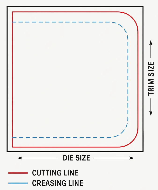
The full structural layout must be presented clearly, including both the die-cut size and the final trimmed size. This is essential for accurate plate making and production. - Use different colors to distinguish process lines
Common industry practices include:- Red for cutting lines
- Blue or green for creasing lines
- Additional colors or line styles for perforation or slitting
Clear color coding helps prevent mistakes during die-making and production.
- Design holes and cutouts properly
- Avoid making holes too small, which can cause tearing or make die manufacturing difficult.
- Do not design sharp points or acute angles, as these weaken the structure and may cause cracking during folding.
- Avoid placing multiple holes too close together; maintain adequate spacing for stability.
- Use continuous cutting lines whenever possible
At corners, rounded transitions (R-corners) are recommended to enhance the integrity of the die and prevent breakage. - Avoid perpendicular blade joints
Excessive right-angle or perpendicular joints increase manufacturing difficulty and may lead to instability during production. Smooth, continuous curves are preferred. - Prevent the start point of one blade from joining the middle of another cutting line
This type of connection creates dangerous sharp points, complicates waste removal, and increases the risk of blade loosening.
The proper approach is to replace such joints with a smooth, continuous arc and position joints along straight sections.
| 0 Comments |
|---|